| Previous | Home | Next |
| Carving The Top |
|
UPDATE!
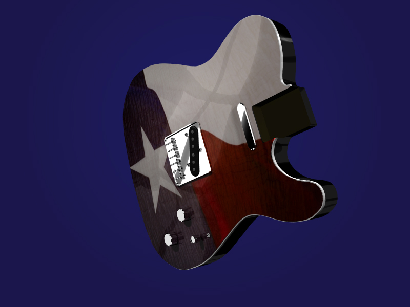
I have gone a different direction with the carve. Here are 2 shots of the final layout. The first image shows the displacement map I used to "carve" the top in software. The lighter the pixels, the more the polygons in the 3D model are pushed forward. The darker ones stay flat. The second image is the result with the artwork mapped onto the mesh.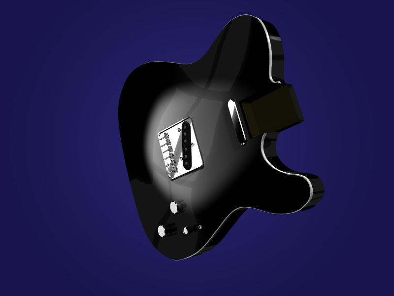
Here we go!!!
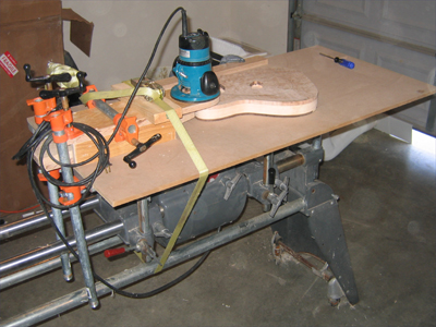
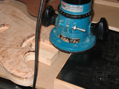
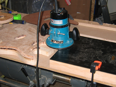
I think I have this figured out now so it's time to start carving. The first this I needed to do was create a large, solid, flat workspace...once again, the Shopsmith Mark V is the answer...slightly modified of course. I bought a second table carriage a month ago to increase my table space for the table saw and it's a big part of this setup. I leveled it up with the main table and extension table and covered them with a 2' x 4' sheet of 1/2" MDF. This gave me a large area to set up the Saw Dust Generator (SDG).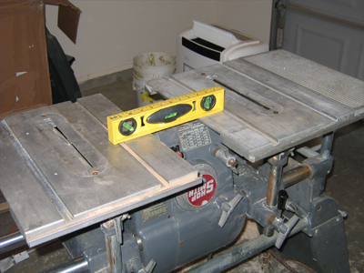
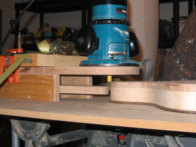
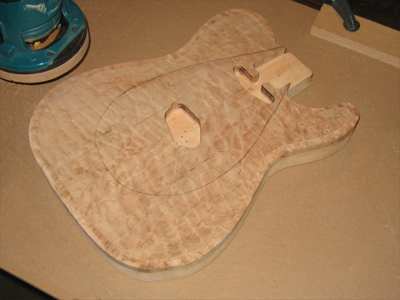
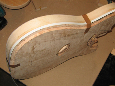
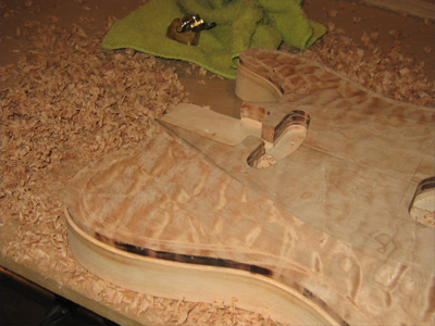
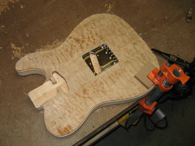
After taking the top to the final depth around the edge, I needed to cut the binding channel. Now in hindsight, I could have done this first but I got a more acurate cut depth this way. I chucked up a piloted bit that has a bearing that ensures a .060" cut. Most of the body was no problem but around the horns there wasn't much to support the router. This is why I don't throw anything out. An alder body blank wasn't quite the right thickness but with some plastic material for making cavity covers, it was perfect! This is a new sheet of plastic, but I can promise you I'll keep even the smallest piece of scrap after I start cutting from it.
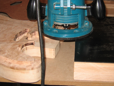
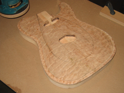
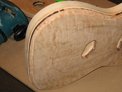
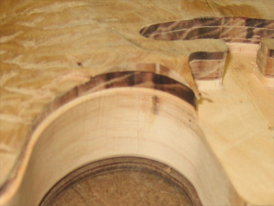
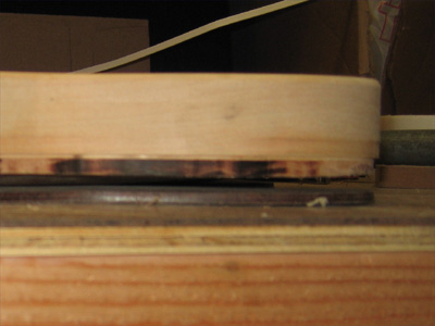
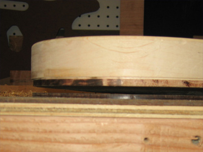
Here's a of the finished binding channel...it's easy to see as it's burned black...I haven't put a blade or bit to this maple yet that hasn't burned it!. And a shot of the binding laid in place. I cut the channel about 1/64" deeper than I needed to allow for carving and sanding the top. Look closly and you can see the binding is slightly shy of the top of the channel.
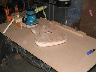
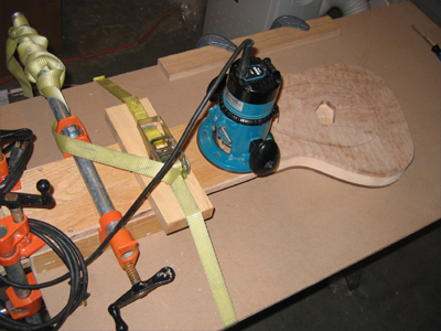
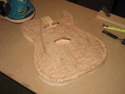
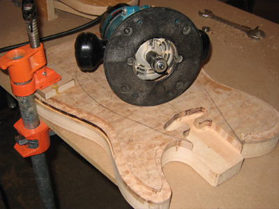
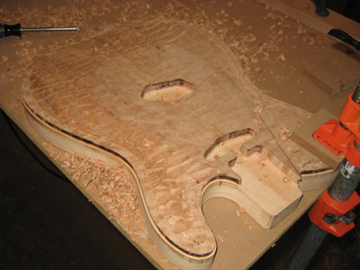
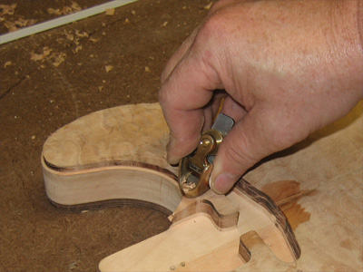
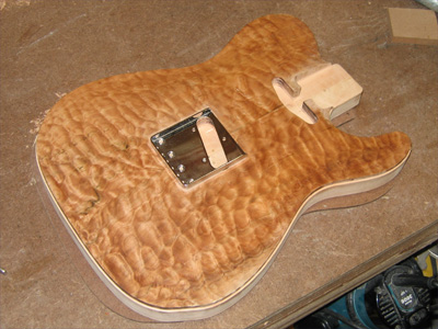
After a second pass through the SDG it's finally time to start carving with my new Ibex finger plane... I could have gone one size larger but after just a few minutes I got the hang of being productive with a small plane. Following are shots at various stages. I worked the whole top down to the closest inside cut then took it down to the outside from there. I haven't decided how I'll finish the inside shape of the carve but it's close as is...probably just roll it into the carve during sanding. And there's a nice flat spot for the bridge...wouldn't want the carve sneaking up under it.
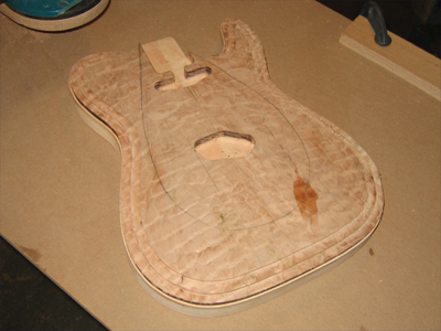
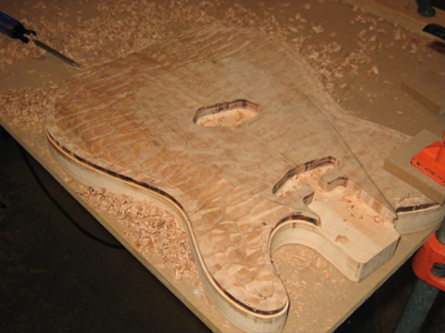
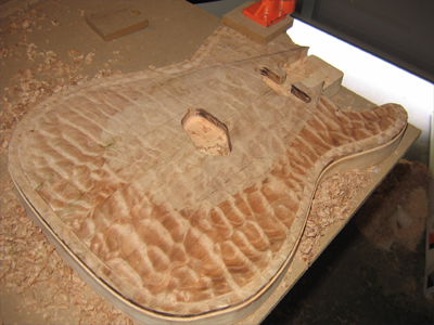
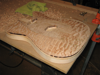
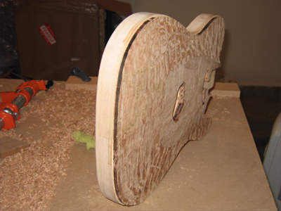
As you can see here, it's a very subtle carve. Just enough the break up the surface and catch some light and reflection...much like the 3D version posted at the top of this page and in this animation.
New Carve Profile
The Carving Continues
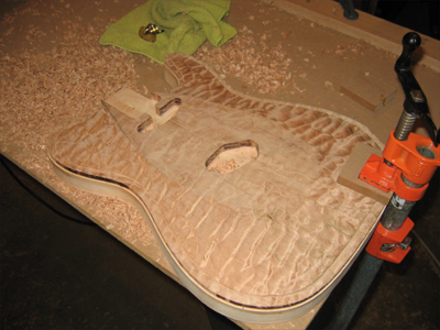
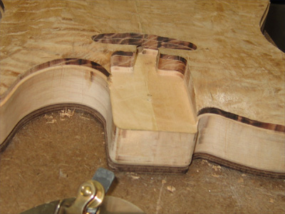
Well, I finall got back to work on the guitar...insulating the garage and dodging the heat have kept me out of the shop. I started back on the carve by taking care of the area around the neck pocket. The issue here is that I didn't want to carve the area around the pock down to the level of the binding channel because this would make the neck look like it was sitting too high in the pocket...showing too much of it's sides. So, I only took down what I had to, to get the edges down to binding level. It made for some steep drop offs but I'm OK with that versus the fummy looking neck thing.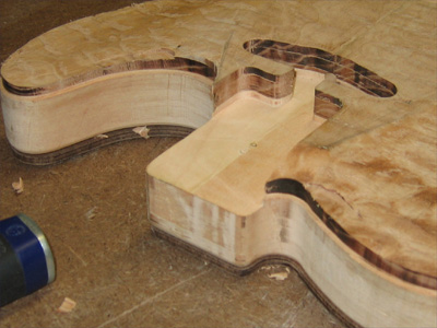
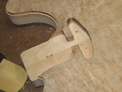
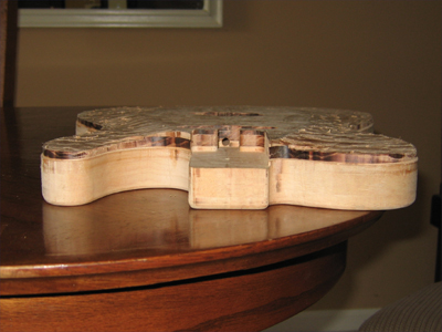
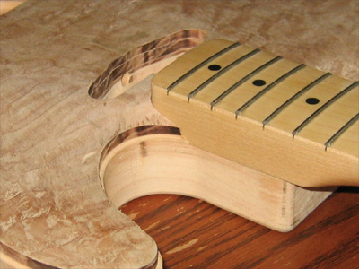
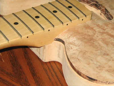
With a neck set into place you can see how the carve looks. I just need to square up the ends.
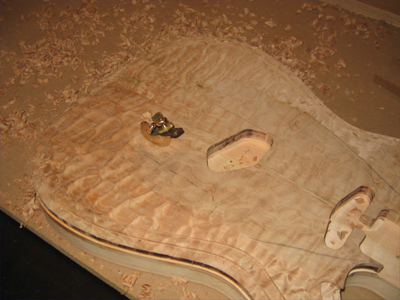
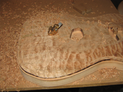
After sorting that out, it's time to smooth out the carve. There is a large flat spot in the center of the guitar that I avoided to make sure I left plenty of room for the bridge...which was taped into position for this stage of the carve. So, I spent some time easing it into the rest of the carve...I'm pretty happy with the results. It still needs scraping and sanding to finish it up but the heavy carving is done.
A little wipe down and cleanup with some Naptha makes that grain pop out!
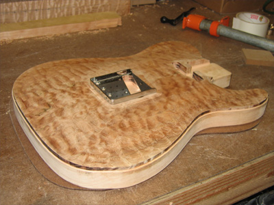
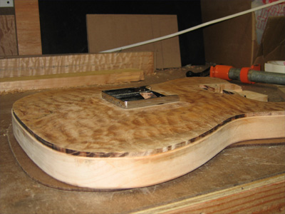
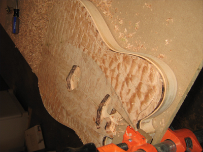
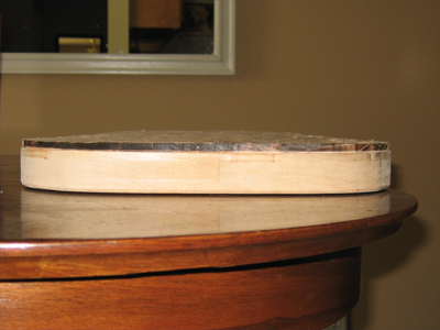
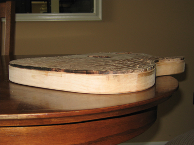
It's tough to see the extent of the carve just yet. Here are a couple of shots with the body lying on it's front...you can see the gaps at the edges.
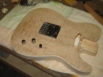
Installing the Controls
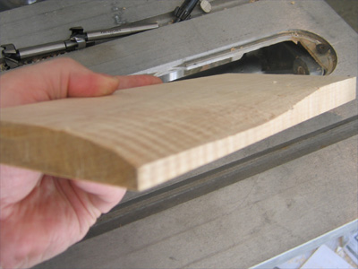
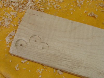
The volume, tone and 3-way switch are next. This part of the project has given me much anxiety. One slip here, and all of my work is wasted. I have to arrive at exactly the right thickness at several different places so that the controls mount and function properly. On a flat top guitar, no problem. On a carved top? Well, I've never done it. Ask me when it's over.I started with the easier 2 of the 3...volume and tone. I wasn't sure how I wanted them to look. I have seen it done several ways and I wanted to experiment with a few options so I did a quick carve on a piece of scrap maple and took a look at various options...more room around the knob, less room around the knob. The bottom of the reccess flush with the top, the knob fully encircled by the reccess.
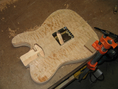
I sued the routing template for the control cavity to transfer it's location onto the front of the guitar...note the pencil marks on the biding for reference. I wanted this so I could see how the exact placement of the controls would look. True, I had already routed the cavity, but I wanted to make the best use of the space I had within it.
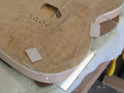
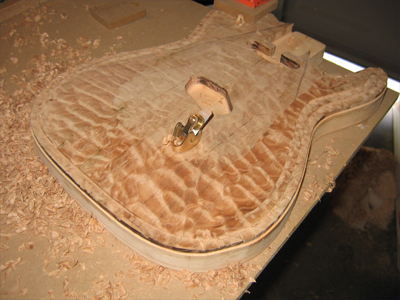
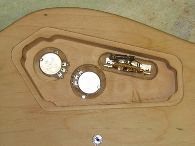
The first step in the layout was to position the switch. I'll talk more about this little block of wood later. Then I could locate the pots and drill them out.
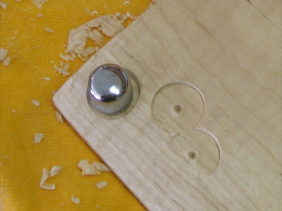
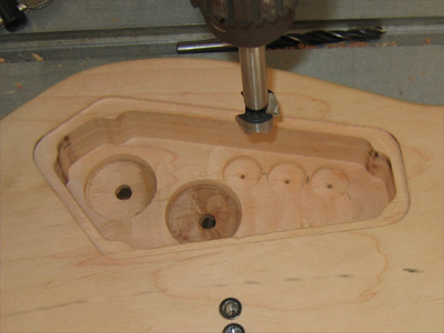
The body where these mount is over 5/8" thick, so I have to bring that tat down to under 1/4". I wnat the pots to sit in the carved top as they would in a flat top...so a level underside is the key. I used a large forstner bit to take the thickness of the body down to about 3/8".
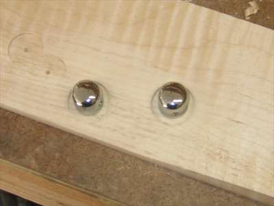
Still not the thickness I need, but I removed the balance from the top by reccessing the pots into the top. The knobs are just sitting in there...they will ride a bit when installed.
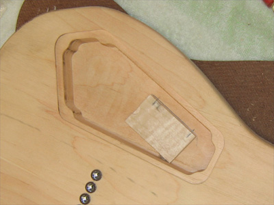
Now, on to the dreaded switch. This is going to require an even thinner mounting surface...a bit thicker than a heavy pickguard. Yikes!!! I decided to make a test fit of the switch in case there were any issues. I could solve them before I'm working down in the cavity.
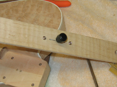
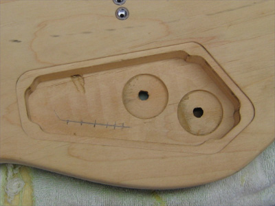
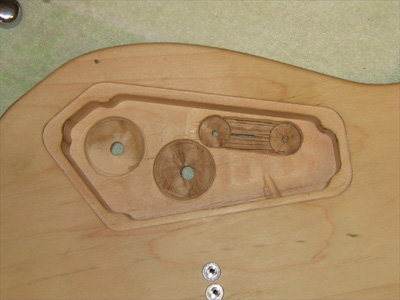
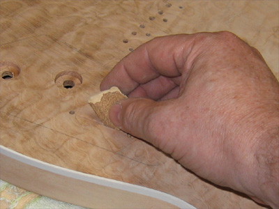
Remember that little block of wood in the control cavity? I was struggling with how to transfer a measuement into that cavity. It's odd how I can think through the toughest of problems, but then a simple thing stumps me from time to time. Then it hit me, make a template. OK, it's not really a template but you get the picture. So, I started with a forstner bit for removing material. The 2 outside holes made by the center guide of the bit, are my mounting holes for the switch.
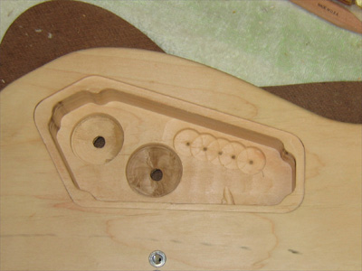
Drilling away every so slowly until I got to a point I was concerned about the center of the bit coming through the top. Then I stopped and turned my attention to the top of the guitar.
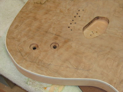
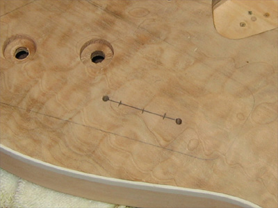
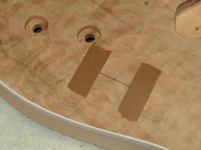
After drilling through the 2 mounting holes, I layed out the slot for the switch. I layed down a few strips of tape at the ends of the slot as a visual guide and then started opening it up with a utility knife. No pics during this, I was in deep "paying attention to what the heck I was doing" mode.
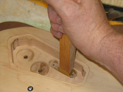
After I got the slot started, it was back into the cavity to remove more wood. I used the 2 mounting holes to deepen the reccess with the forstner bit, then I removed the middle with a chisel...breaking up the surface with a utility knife so the chisel wouldn't gouge down. Then at each step I would place a bit of 100 grit on the end of an oak stick and sand the bottom smooth.
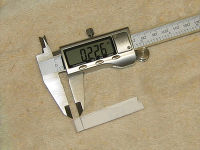
I checked the remaining thickness of the top by sliding a strip of paper into the slot and folding over inside, then I marked the outside with a pencil...removing the paper and measuring with calipers, between the fold and the pencil line, gave me the current thickness at each stage.
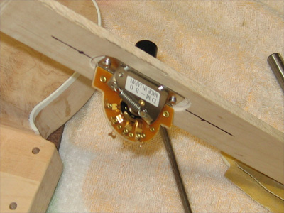
Once I got to the depth I wanted, I returned to the top to widen the slot. First with a single layer of 220, then folded double, then a single layer of 120, then folded double and so on until the switch slid in and moved back and forth easily. I had to remind myself to sand perpendicular to the back of the guitar, not the front. The switch needed to come through the slot at an angle because of the slope of the carve from one edge of the switch to the other...remember, it's mounted flat in the control cavity.
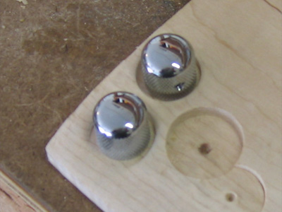
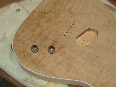
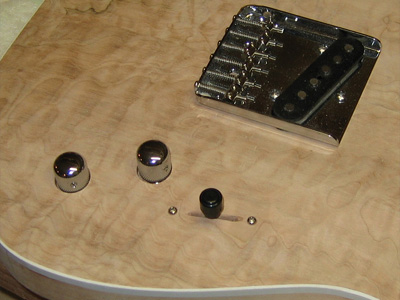
Coming to the successful end of this phase gave me great satisfaction and even more refief. Looks good front and back. I might still round over the edges of the knob reccesses but I'm not sure. I'm kinda diggin' the "clean entry" look. What do you think???
| Previous | Home | Next |